Overview
DDOE offers an advanced LiDAR (Light Detection and Ranging) annotation and detection tool. By loading supported LiDAR files into the DDOE platform, annotators can label and segment out objects captured by pulsed lasers, and provide precise three-dimensional information for data scientists and industry professionals to build AI models for cutting-edge applications.
Upload LiDAR items
In DDOE's LiDAR Labeling Studio, you can upload and work PCD data. To upload, see the Upload Items articles.
Supported file formats are PCD and JSON files. Learn more about the specifications.
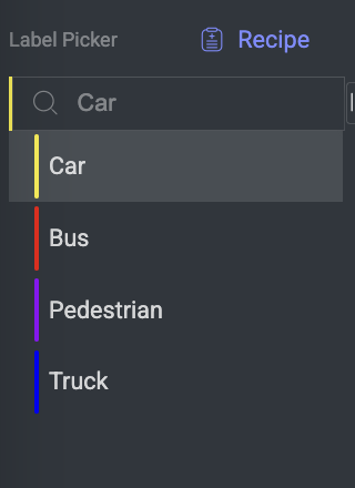
Label Picker
The Label Picker is a feature within the annotation studio that allows the annotator to select labels to assign to specific objects or elements in the data being annotated. The available labels are determined in the Recipe.
LiDAR Tools
The following annotation tools are available for the LiDAR studio:
Create 3D Cuboid Annotations
The tool is designed to annotate objects in 3D point clouds with cuboid-shaped bounding boxes. These bounding boxes represent the spatial extent and orientation of objects within the three-dimensional scene. Annotators use the 3D Cuboid Annotation Tool to draw a cuboid around an object of interest in a 3D point cloud. This cuboid typically represents the minimum bounding box that encloses the object while providing information about its three-dimensional size.
The 3D Cuboid Annotation Tool is especially valuable when dealing with objects that have a three-dimensional structure, such as vehicles, buildings, etc.
Only on LiDAR Annotation Studio
3D Cuboid annotations are supported only on the Lidar Annotation Studio.
Select the Cube 3D annotation tool from the annotation tools.
On the canvas, left-click and drag to create the cuboid you want to annotate.
A cuboid will be created, the annotation will be added to the annotations list. Subsequently, the canvas will display the annotation.
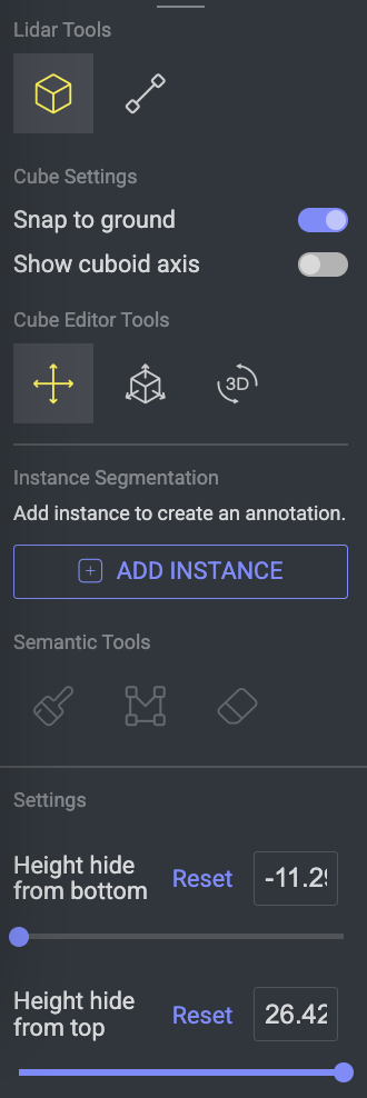
Additional Cuboid options:
Snap to Ground: By default, this option is active. A new annotated cuboid will be annotated adjunct to the ground while active. This option allows fixation on the ground.
Show cuboid axis: Enable it to display the cuboid axes on the canvas. This feature enables the visual representation of the cuboid's axes for better orientation and editing.
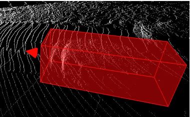
Directional Heading
The directional heading arrow intends to allow the annotator to indicate the ego vehicle facing. The annotator can adjust the direction of the arrow by rotating the cuboid.
Create 3D Polyline Annotations
A polyline is a continuous line composed of one or more line segments. In data annotation, it's represented as a series of connected points, where each point is defined by its coordinates (e.g., x, y for 2D spaces, and x, y, z for 3D spaces).
3D Polyline annotations are supported only on the LiDAR Annotation Studio.
Polyline Line Type
If the polyline is spline, then the line type is spline in the JSON file output.
if the polyline is linear, then the line type is linear in the JSON file output.
Choose the Polyline annotation tool from the available annotation tools.
On the canvas, locate the starting point and initiate the polyline by left-clicking with the mouse.
Identify the endpoint and left-click with the mouse to define it.
Press Enter to finalize the annotation. The polyline will be generated on the canvas and added to the list of annotations. The starting point of the annotation will be highlighted in green.
Adjust the Line Width as required.
Annotate Using Spline Polyline
Spline: It allows annotators to create a curve or line segment that has the characteristics of a spline. Annotators can manipulate control points to shape the curve as needed, creating aesthetically pleasing and precisely defined paths.
Select the Polyline annotation tool from the available annotation tools.
Activate the Spline feature.
On the canvas, locate the starting point and initiate the polyline by left-clicking with the mouse.
Identify the endpoint and left-click with the mouse to define it.
Press Enter to complete the annotation. A curved polyline will be generated on the canvas and added to the list of annotations.
Adjust the Line Width as required.
For Spline Polylines
For the spline polylines, a gray color point will be added to define as the center point. Select this point to adjust the polyline as needed.
Once you click and move the gray point, it becomes as a new permanent point for the polyline with another two gray dummy points will be added as center points. Refer to the following GIF example for a clear understanding of it.
Switch to the Polyline Spline Feature in the Annotation
You can switch an existing polyline annotation to a spline annotation.
Choose the Polyline annotation tool from the available annotation tools.
Enable Spline feature. The normal polyline annotation will be converted to spline polyline annotation.
Create 3D Instance Semantic Annotations
Instance segmentation annotation involves color-coding the pixels within an image or, in the case of LiDAR data, the point clouds. As the name suggests, instance segmentation focuses on annotating individual instances, enabling the differentiation of objects that might share the same label. Instances feature allows annotators to add more annotations using the same label.
Note
Instance Semantic is supported only on the Lidar Annotation Studio.
You can create a new instance, even if there are no segmented points.
When an annotation is added, the instance will exist, but it will not contain any segmented pixels.
Using Brush Applicator
To activate instance semantic annotation using the brush applicator, follow these steps:
Select the label from the label picker.
Click Add Instance. An annotation is created in the annotation list.
Select the Brush icon from the semantic tools list.
Utilize the left mouse button to delineate and segment the specific points or objects of interest on the canvas. Displays a chip message immediately after segmentation is created on specific points.
Utilize the Brush Size to customize the brush size according to your preference.
Note: Override is restricted in segmentation
When adding a segmentation layer to point clouds, any points that are already part of an existing segmentation instance will be automatically skipped. You will receive a notification informing you which points were not added to avoid duplication.
Erase the Brush Annotations
To activate instance semantic annotation using the brush applicator, follow these steps:
Select the Brush and Eraser icons from the Semantic Tools.
Identify the brush annotation and utilize the left mouse button to erase it. The annotation will be deleted from the annotation list.
Utilize the Eraser Size to customize the eraser size according to your preference.

Using 3D Polygon
3D polygon annotations extend the concept of marking areas of interest into the three-dimensional space. The annotation of LiDAR data involves the utilization of the 3D polygon tool, particularly in cases of instance segmentation where the same tool is employed.
Select the label from the label picker.
Click Add Instance. An annotation is created in the annotation list.
Select the Polygon to Instance tool under the instance semantic section.
Create the outlines of your annotation by clicking with the left-mouse button. In the polygon, the first point is marked in green to indicate it is the first point.
Complete the polygon by connecting the first point to the last point, or click Enter. Upon completing the outline, the instance semantic annotation will be generated.
Erase 3D Polygon Annotations
To activate instance semantic annotation using the brush applicator, follow these steps:
Select the Polygon to Instance and Eraser icons from the Semantic Tools.
Identify the polygon annotation and utilize the left mouse button to erase it.
Complete the polygon by connecting the first point to the last point, or click Enter. Upon completing the outline, the annotation will be deleted from the annotation list.

Instance Semantic JSON Output
The following JSON output provided is part of a semantic indexing system for organizing data by frames. Specifically:
"semanticIndex": {
				"type": "index",
				"frames": {
					"5": [
						3197,
						3198,
						3199,
						3201,
						3202,
						3203,
						3204,
						3205,
						3206,
						3207,
						3208,
						3209,
						3210,
						3211,
						3212,
						3213,
						3214,
						3456,
						3457,
						3458,
						3461,
						3462
						],
						}
semanticIndex: Labels the structure as a semantic index.
type: Indicates that this is an indexing system.
frames: Organizes the indexed data by frames.
5: Refers to frame number 5, listing identifiers (like 3197, 3198, ... 3462) which likely represent specific objects or annotations within that frame.
2D Editor - Camera View
The 2D Editor displays Cuboid and Polyline annotations projected on the image, while the annotation location on the PCD file corresponds to their position on the image. It is the visual assistant for corresponding images that showcase both the angle and the viewport of the cameras captured by the main scene.
Instance Segmentation projection on 2D is not available.
To open the 2D editor, hover over the desired image on the right-side panel and click Open 2D Editor.
Upon opening the 2D editor, you will have access to a range of capabilities, including:
Selecting annotations within the Image view.
Editing annotations, which includes modifying the annotation ID.
Deleting annotations.
Adjusting the scale, rotation, and translation of the annotation, effectively alters the geometry of the 3D cube.
Setting the end time for the annotation.
In order to exit the 2D Editor, click ESC or Exit 2D Editor on the right-side panel.
Fisheye Camera Images
DDOE’s LiDAR Annotation Studio now offers full support for fisheye camera images, enabling powerful 3D annotation workflows with wide-angle visual data. This integration allows accurate alignment between LiDAR point clouds and fisheye imagery, removing the need for manual distortion correction or preprocessing.
Key Capabilities
Annotation Alignment with Fisheye Projections
When annotating LiDAR data over the PCD file, the system intelligently adjusts annotation rendering to match the fisheye lens distortion. This ensures that bounding boxes remain accurate and visually aligned, even across heavily distorted fields of view.Sensor Fusion with Fisheye Inputs
DDOE enables sensor-fused annotations by combining LiDAR and fisheye camera data with automatic distortion correction. Users can also edit 3D LiDAR annotations directly from the 2D fisheye view.No Manual Undistortion Required
Unlike traditional workflows, there's no need to preprocess or undistort fisheye images externally. The system handles fisheye projection natively, simplifying your pipeline and reducing potential calibration errors.
How It Works
The DDOE platform overlays LiDAR annotations on fisheye images by:
Accepting calibration metadata in JSON format
Applying intrinsic (lens-specific) and extrinsic (pose-specific) camera parameters
Triggering fisheye rendering logic only if
intrinsicDatacontains non-zero values
How DDOE Uses the Data
If
intrinsicDatais present and not all values are 0, DDOE recognizes the image as fisheye.The fisheye rendering engine undistorts the image using the intrinsic model.
The annotations (bounding boxes, segmentation, points, etc.) are then projected from LiDAR space into 2D image space based on the
extrinsictransformation matrix.
Upload the JSON File to the Dataset and Start Annotating
Upload your calibrated
frames.jsonto the datasetAnnotate PCD files as usual
Fisheye camera views will render annotations in Scene Editor and Camera View automatically
mapping.json– This file is provided by the customer and contains the calibration and sensor configuration data.frames.json– This is the video descriptor file used to open the studio. It references and utilizes the data defined inmapping.jsonfor visualization and annotation.
Refer this link to start the Annotation process.
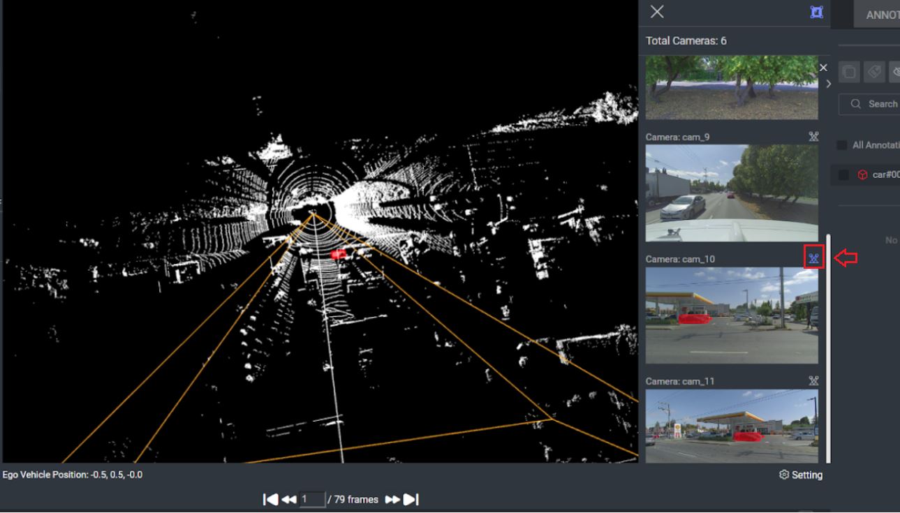
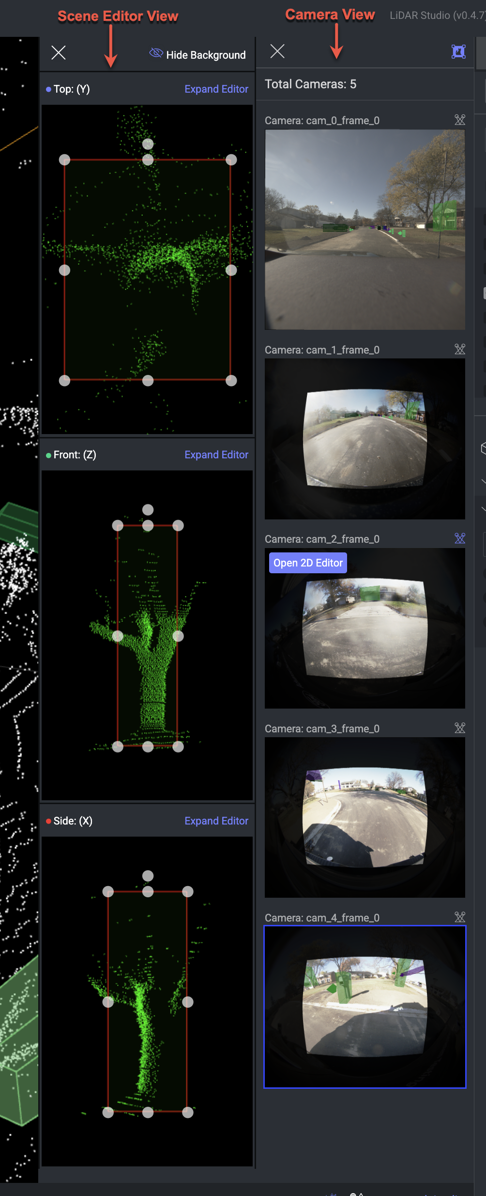
Use the Scene Editor View and Camera View to Make Changes
It allows allows you to visualize fisheye camera images with annotations overlaid. This is especially useful for validating and refining annotations added to your PCD files:
Click on an annotation in the PCD file.
The corresponding camera views will automatically appear in:
Scene Editor View
Camera View Panel (located on the right side of the PCD canvas)
To modify annotations directly within a camera image:
Click on the camera image in the Camera View panel.
The image will open in the main canvas.
You can now edit the annotation as needed (e.g., move, resize, adjust orientation).
To make adjustments in 3D space:
Select the desired perspective (e.g., Top, Front, Side) from the Scene Editor.
Modify the annotation in the selected view using standard editing tools (translate, rotate, scale, etc).
Projection
The projection signifies the angle at which the camera captures data within the PCD file. Activate the projection by clicking the button on the 2D Editor panel.
3D Editor - Scene Editor View
Selecting a Cuboid annotation from the annotations list opens the 3D editor, displaying the cuboid in three dimensions and enabling users to easily edit it.
To hide the Point Cloud Background points, utilize the Hide Background button.
Expand the 3D editor to obtain a larger view of the annotation.
Zoom to Mouse Cursor in LiDAR Side Panel
Annotators can now zoom directly to the mouse cursor in the 3D Camera View. This feature allows for more precise navigation and focus on specific areas within the LiDAR data, enhancing the efficiency and accuracy of the annotation process.
Settings & Features
Height Hide from Bottom or Top
Utilizing these filters enables you to refine the display of point clouds on the canvas according to their height, simplifying the process of identifying and annotating objects. This hide height feature is essential while annotating with Instance Semantic Segmentation. Read more about it on the instance segmentation tool.
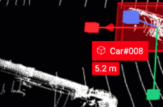
Annotation Controller
The annotation controller directs the annotator to the specific annotation being viewed on the canvas. The annotation controller will display on the canvas by selecting the annotation from the list.
Hover over the annotation name to perform the following actions with the Annotation Controller:
Set end time: You can set end time for the annotation based on the frames.
Set object ID: You can add a unique ID for the annotation.
Delete Annotation: Click on the trash icon to delete the annotation.
The distance below the annotation controller presents the distance of the annotation from the PCD file center.
Navigate Annotations
Lidar annotation studio allows you to navigate annotations around the canvas. You can perform the following actions on the LiDAR studio:
Move UP and Down: Click on the purple arrow to adjust the height of the annotation.
Move Sideways: Click on the green and red arrows to move the annotation sideways accordingly.
Drag Annotations: Click in the center of the annotation, and drag it to move it to a new location.
To pan the canvas, press Ctrl+drag.
To activate anchor mode and change the point of view angle, press the Space bar + drag. The anchor mode will present a sphere in the center of the screen. When zooming in, the zoom-in will be done relative to the center of the screen.

To learn more actions, click on the Keyboard Shortcuts or refer to the Keyboard Shortcuts.
Frames Navigator
This feature is designed to facilitate navigation and interaction with different frames of LiDAR data. If the LiDAR file comprises a sequence of frames, you can switch between PCD frames. The selected frame's scene will be showcased on the canvas, and the 2D images of that scene will be synchronized accordingly.
Loading Frames
The platform can simultaneously load five frames: two frames ahead, two frames behind, and the current frame.
For example, In the instance where you are positioned on the 5th frame within a sequence of 10 frames, the platform will concurrently load frames 3, 4, 6, and 7. Loading times apply for frames outside this immediate range.
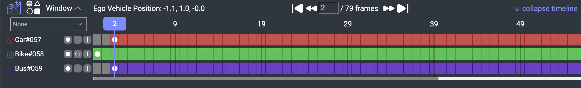
Ego Vehicle Position
The Ego Vehicle position refers to the position of the ego vehicle within the PCD file, and is precisely centered within the PCD file. The ego vehicle is typically the vehicle on which the LiDAR sensor is mounted. It serves as the reference point for interpreting and analyzing the surrounding environment based on the LiDAR point cloud.
Show / Hide Ground
When this feature is enabled, the ground is displayed. By default, it is enabled, and the ground is visible. Clicking it causes the ground to disappear.

Ground detection
Ground detection is supported exclusively for sequence files and not for individual frames. If the PCD file consists of a single frame, the annotation will be positioned at the z-axis origin.
Show or Hide Attributes
When this button is activated, the attributes of the annotation are shown over the item, next to each annotation. By default, it is deactivated. Clicking it will reveal the attributes.

Timeline
The timeline enables users to visually observe annotations and their corresponding frames. By default, the timeline feature is in a collapsed position. Clicking Expand Timeline will reveal the timeline, displaying a maximum of 5 annotations at a time, with scroll functionality.
Timeline is unavailable for single-frame files
If your file consists of only a single frame, the timeline feature will not be available.
Linear Interpolation
Linear Interpolation automatically calculates the linear change of size and position between two keyframes, allowing users to speed up work by eliminating the need to make small changes on every frame. By default, Linear interpolation is active in the LiDAR studio. If the dropdown value is “None”, then the interpolation tool is inactive, and the created annotation won’t be interpolated.
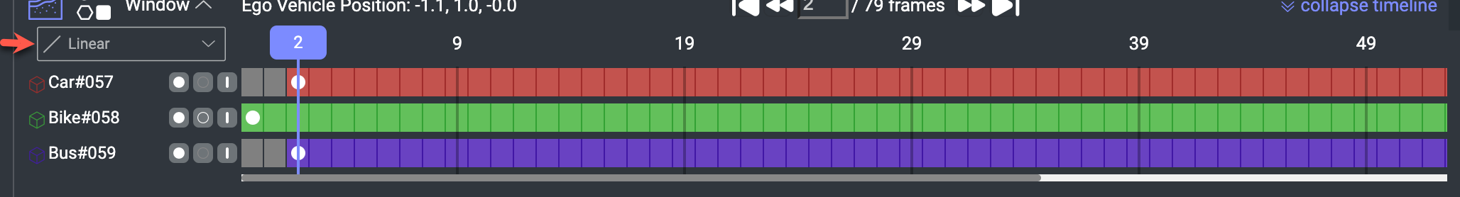
Linear interpolation is supported for 3D Cube and Polyline.
Cuboid: Cuboid annotation tool supports interpolation. If the interpolation is enabled, the annotator can annotate and the interpolation will be done automatically. Between each 2 keyframes there will be interpolated frames.
Polyline: The polyline annotation tool supports interpolation. When activated, annotators can annotate, and automatic interpolation occurs between consecutive keyframes. The polyline points can be adjusted at each frame, with any modification treated as a keyframe (including attribute, label, and location changes).
Instance Semantic: Instance semantic annotation tool does not support interpolation. For annotating with Instance Semantic on various frames, the user should annotate manually at each frame. Each manual annotated frame will be counted as keyframe.
Important
If you use the Instance Segmentation tool for the annotation, the Set Start Time, Set End Time, and Set Hidden/Visible Mode buttons will be disabled.
Use the controls on the left to set a keyframe at the current position.
Set Start Frame: It removes the previous Start Frame.
Set End Frame: The annotation will end on this frame.
Set occlusion on/off: Set ON when the annotation is hidden and off when it's back. Changes are visualized over frames with different opacities.
Annotations Tab
The Annotations tab on the right-panel allows you to control and manage annotations involves utilizing the annotations list and attribute controls, particularly when attributes are configured in the Recipe.
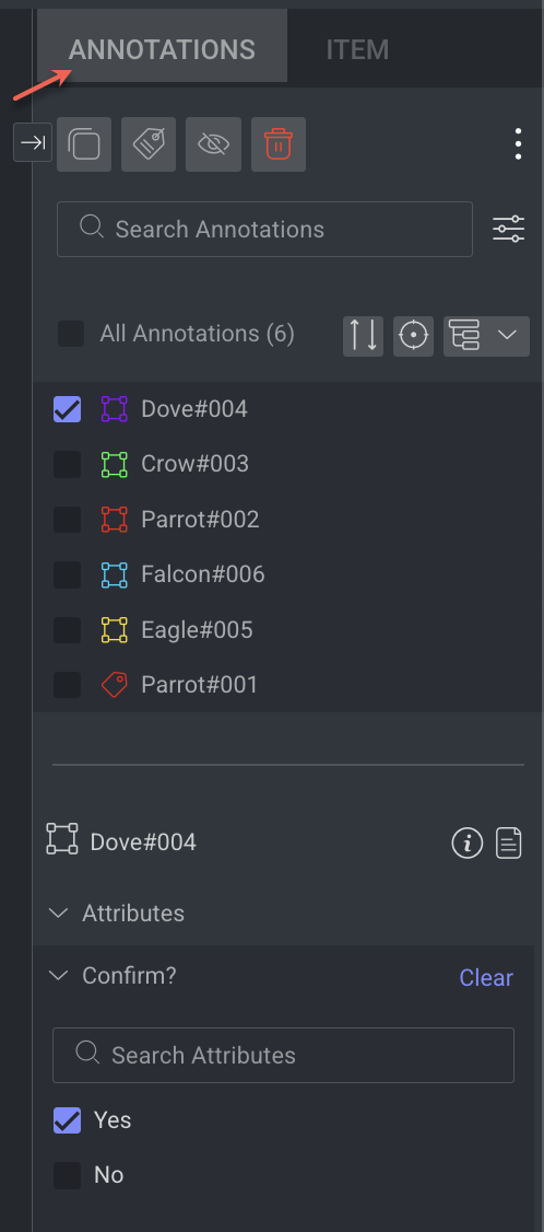
Learn more about the annotations and actions available.
Item Tab
The Item tab displays information according to the type of the selected item.
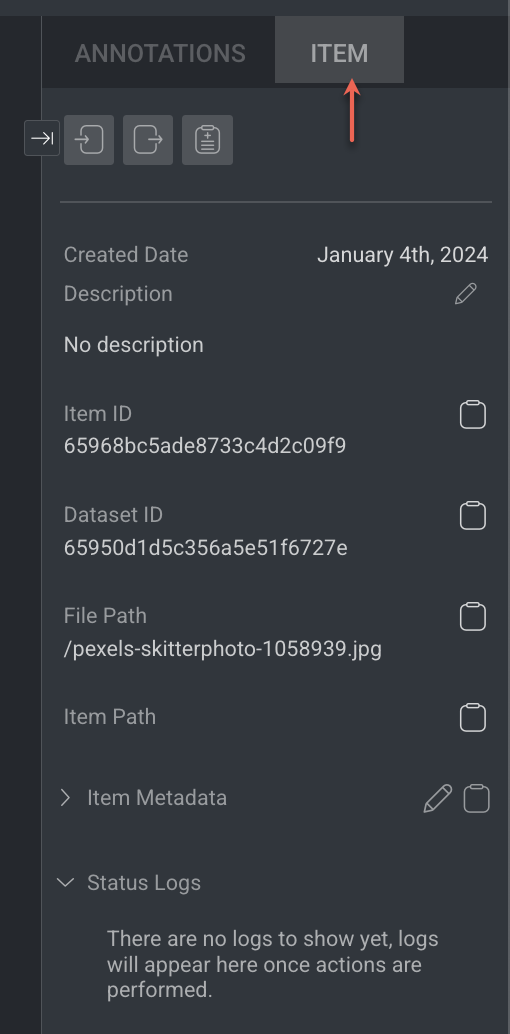
Learn more about the item and actions available.
Item Info & Controls (top-panel)
Item Info & Controls are available depends on the type of annotation studio. For the detailed information, refer to the following articles.

Window
The Window settings panel enables you to view the scene editor and camera perspectives for the PCD file along with its annotations. It also provides tools for making adjustments such as editing, rotating, and positioning annotations.
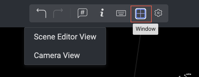
Once you select the views are displayed as shown below:
Settings
The setting configuration is available on top of the LiDAR studio.
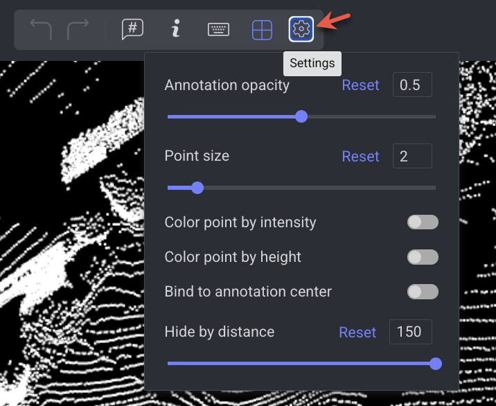
Annotation Opacity: Users can adjust the opacity of annotation to have a better sight of the PCD scene.
Point Size: Users can adjust the point cloud size. Resizing the point cloud will help annotators to have a clearer view of the Point Clouds.
Color Point by Intensity: Intensity serves as a valuable tool for visualizing the strength of laser returns within a LiDAR point cloud.
Color Point by Height: Coloring points in a LIDAR point cloud by height is a common visualization technique that helps convey information about the elevation of the terrain or objects. This feature assigns colors to points based on their height values, where lower points are colored with green color and higher points are colored with red color.
Bind to Annotation Center: Upon enabling this configuration, it will impact the distance-based hiding behavior. When activated, the concealed area will be relative to the center of the chosen annotation. Conversely, with this configuration turned off, the hidden area will be relative to the PCD center.
Hide by Distance: By adjusting this scale (in meters), the canvas will filter out points that are not within the distance range.
Keyboard Shortcuts
General Shortcuts
Action | Keyboard Shortcuts |
|---|---|
Pan | Ctrl + Drag |
Anchor mode | Click + Hold Space bar |
Zoom in/out | Scroll |
Save | S |
Delete | Delete |
Undo | Ctrl + Z |
Redo | Ctrl + Y |
Hide/Show selected Annotation | H |
Hide/Show All Annotations | J |
Deselect annotation | Enter |
Zoom inwards | Q |
Cuboid Translate mode | W |
Cuboid Scale Mode | E |
Cuboid Rotate Mode | R |
Object Top view | S |
Object Side view | D |
Object Front view | F |
Previous Frame | < |
Next Frame | > |
Item description | T |
Exit 2D Editor | Esc |
Go to annotation list | Shift + ; |
Navigate in annotation list | Up and Down arrows |
Select/deselect an annotation | Space |
Annotation Tools Shortcuts
Action | Keyboard Shortcuts |
|---|---|
Create 3D cube | Left Mouse click + Drag |
Semantic Polygon | Select the Polygon + Left Mouse Click |
Semantic Brush | Select the Brush + Left Mouse Click |
Item's View Controls (bottom-panel)
The controls on the bottom-side panel display based on the annotation contexts and work controls.

Workflow Context
Assignment controls, including moving between items, displaying the item gallery, and the status buttons (Complete / Discard). It displays only while working on an annotation or QA task.
Browse between the assignment items using the Left and Right arrows
Open the Thumbnails' gallery viewer, and click a thumbnail to open that item
Save button - Clicking the button when it is enabled triggers saving changes to the DDOE platform, before the auto-saving feature takes care of that.
Status buttons - Complete and Discard.
View Controls
Frames navigator
Items thumbnail
Show/Hide Attributes
Show/Hide ground
Clone LiDAR Files
When you clone a LiDAR file (frames.json) from the Dataset Browser using the right-click -> File Actions -> Clone option, it does not properly clone the file completely. This method may result in incomplete cloning, leading to potential issues with data integrity and usability.
Ensure you use the following method to clone the LiDAR files accurately:
In the Dataset Browser, download the frames.json file.
Re-upload the Frames.json file to the dataset.
In the dataset browser, select the original file again.
Go to the Metadata tab in the right-side panel.
Click on the Pencil icon.
Copy the
shebangdata.
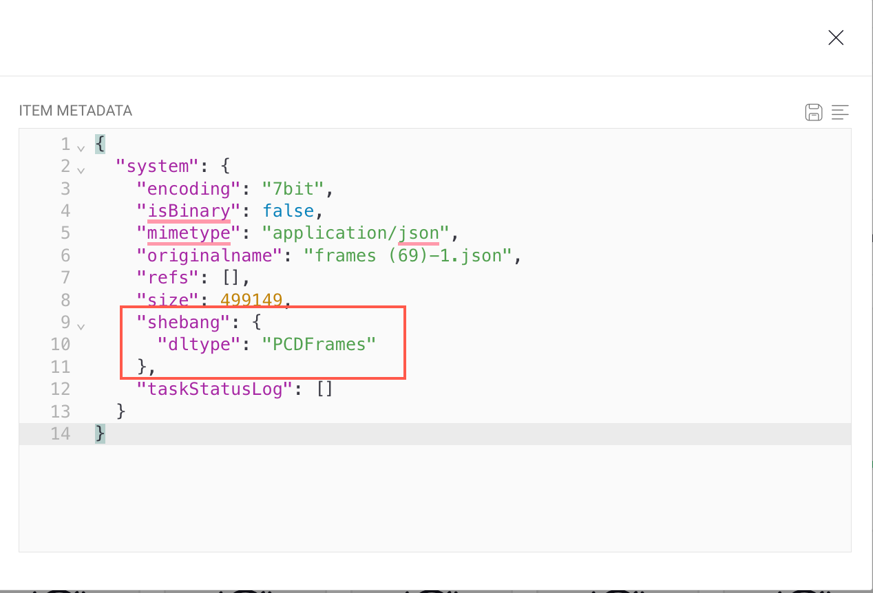
Navigate back and select the newly cloned item.
Go to the Metadata tab in the right-side panel.
Click on the Pencil icon.
Paste the
shebangdata under the system section.Click on the Save icon.
Edit and Delete Annotation
Select the annotation from the annotation list.
To Edit: Hover over the annotation and click on the pencil icon to make the changes.
To Delete: Click on the Trash icon to delete.
Edit a Specific Instance
Select the instance-annotation from the annotation list.
To segment more points with this instance, keep annotating following the above instructions.
LiDAR JSON Format
To learn about the LiDAR JSON format, see the LiDAR JSON Format page.